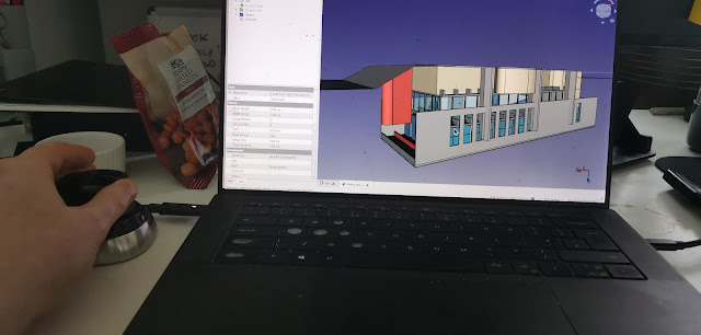
As you’ve probably seen from my Twitter posts, I recently started my journey with the SpaceMouse. I began with the initial setup a couple of days ago, and today I’m attempting to get it working with FreeCAD. I’m sharing my thoughts in real time as I go, so you’re getting my reactions as I discover how this new technology works. Each session lasts around 30-45 minutes.
Currently, I’m still on Windows, and I noticed that a small 3Dconnexion Home window appears every time I turn on my laptop. I initially missed the “show at system startup” checkbox, so I unchecked it to prevent this pop-up.
3Dconnexion provides a knowledge base article on SpaceMouse settings for FreeCAD, but it only covers versions up to 0.21.2, and there doesn’t seem to be anything specific to FreeCAD v1 (RC) yet. Here’s the link: 3Dconnexion SpaceMouse Settings for FreeCAD.
To get started, I powered on the SpaceMouse, opened FreeCAD v1 RC2, and loaded the BIM example found on the start page to explore the settings. Surprisingly, it just worked right out of the box! I expected to need some configuration, but everything seemed to function seamlessly.
Let me tell you, it’s hard to take a first-person photo while using one hand to control the device, holding the camera, and tapping the screen! I have no idea how kids manage it so effortlessly.
For those who know me, you know I can’t stand it when things don’t work, or when instructions tell me to open some “XYZ manager” without explaining where it is or how to find it. This frustration is actually why I started my YouTube channel. But so far, the SpaceMouse has been refreshingly simple to use, although I’ll be looking at the configuration options in more detail later.
As a test I set myself a little challenge: navigating around the building, entering through a door, wandering inside, and then exiting. The out-of-the-box controls are intuitive:
- Pull up/down to move in that direction.
- Twist clockwise/counterclockwise to yaw.
- Push forward/back to move forward/backward.
- Tilt forward/back to pitch.
- Tilt left/right to roll.
Clicking the left or right button brings up a radial menu at the cursor position with options like “views,” which I often used to reset after accidentally zooming too far away.
 |  |
The sensitivity out of the box feels quite high. I found that keeping my palm elevated and gripping the device with my fingers and thumb, rather than resting it on the table like a regular mouse, offered more control. Using an armrest made the experience much more comfortable.
Overall, getting used to the SpaceMouse requires a bit of patience—something 3Dconnexion warned me about. After 20 minutes of trying to walk through the door and up the stairs to the second floor in my model, I started to get the hang of it. The stairs have a landing and switchback, and I initially struggled with turning around without accidentally tilting up, which would leave me facing a wall or losing the model entirely. With more practice and some adjustments to sensitivity, I’m sure the experience will become smoother.
One thing that I have seen on the suppliers website is for the supported software you can customize the radial menu and hook it up to, say, the part design and sketcher operations. This is true for both the 3Dconnexion Spacemouse and the 3Dconnexion CADMouse (Customization for FreeCAD).
In my next sitting I will like to explore these customizable features.Related Posts in This Series:
Thanks for following along with my 3Dconnexion journey! Stay tuned for more insights and tips on using these devices to improve your workflow. Got questions or experiences to share? Drop a comment below!

Hello, It is very good quality of teaching that you offer. Much appreciated by a 3d hobbyist like me. In some of your videos you display a flowchart for modelling process and I think it would be great if this could be a PDF file that could be in a single place on your blog or YT channel. I hope they make an award for work helping more people to embrace open source tools! R
ReplyDeleteHi,
ReplyDeleteI watch your FreeCAD videos to learn the interface, very informative and easy to follow.
I am a Catia V5 / Mastercam user in my professional life, I also use the spacemouse, they are an excellent piece of hardware once you grasp the concept and tailor the controls to the software package.
The skills I use daily are transferable from both of my main cad/cam packages and with the help of your tutorials I have begun to grasp the fundamental basics of FreeCAD and its user interface. It’s somewhat like Catia and Solidworks however the application does have its quirks.
However I am having difficulty with fillets failing to apply on a model.
Particularly with the Solidworks model mania 2000 exercise.
If possible could you do a video using the model mania 2000 drawings with the fillets applied, I believe this would be extremely helpful as an intermediate tutorial for FreeCAD users.
At the moment my own version of the model doesn’t have the fillets as they fail to generate.
Thank you for your work and videos teaching FreeCAD.
Regards
Bodrin.