Let’s explore how we can use the mouse with FreeCAD. I decided to set it up for sketching. While I know I can use shortcuts, not everyone can remember the many key combinations.
Clicking the menu button in the middle of the mouse while in the Sketcher opens the radial menu. This menu is customizable—simply select "Properties" to tailor it to your needs.

Notice how the menu defaults to FreeCAD, the application you're currently using. The software intelligently switches between the applications you have running.
Interestingly, it even detected Screenpresso, the tool I use for taking screenshots. This made documenting the process a bit tricky—after taking a screenshot, the mouse would switch to configuring Screenpresso instead of FreeCAD.

Clicking on the buttons takes you directly to the configuration section for the specific part of FreeCAD you're working in—in this case, the Sketcher.

This is where you can configure the radial menu and other mouse buttons. In true determined fashion—and refusing to read the manual, as any self-assured person might—I dove straight in. I opened the dropdown menu, which offered a wealth of options to choose from. Navigating to the Sketcher folder, I decided to click on one of the options to see what it would do.


Then I clicked "Close." The moment I did, I realized my mistake—I had just set the entire radial button to a single constraint: Horizontal/Vertical. While it worked perfectly, it wasn’t what I wanted.
Now the button that used to pop up the menu was assigned solely to the constraint, and I couldn’t access the menu anymore! To fix this, I had to go to the taskbar, open the menu, and select the cube icon to access the 3Dconnexion Settings.

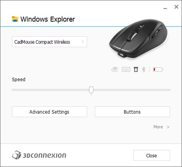
I might be in a different program, but by simply switching back to FreeCAD, the settings window minimizes to the taskbar. You can click on it again to maximize it, and it will have switched back to FreeCAD.
Clicking on "Button" takes you back into the Sketcher configuration.
This app truly shines when you have two monitors. You can move the app to one monitor and seamlessly switch between apps or screens while keeping it open. That’s why there’s no "OK" button—it’s designed to stay accessible as you work.


On the right-hand side, you'll see a series of fields, each with an arrow. This is where you can add your most-used and favorite tools. Click the arrow at the end, select FreeCAD > Sketcher, and find your tool. You can also use the search function to make it easier.

The fields also allow you to type a shortcut for operations that don't have an icon. This is where my mind started to wander. One thing that can be a bit annoying when using FreeCAD is the constant back-and-forth between workbenches. For example, I often use the Clone tool in the Draft workbench within Part Design to clone sketches for lofts and pipes. This is helpful when I need the same sketch but with adjustments to scale along different axes.
I could set up the Part Design radial menu to streamline this process, eliminating the need to navigate to another workbench. I don’t see why this wouldn’t work. The alternative would be to add the tool to the toolbar, but that’s not ideal for me since I create tutorials for FreeCAD with the default settings. It would require swapping configurations if I needed to do work in between. This radial menu solution might be exactly what I’ve been looking for!
Back to configuration: I added what I felt were the most-used tools to the radial menu and saved them for future use.

Comments
Post a Comment