This is a quick tutorial of how to make organic structures in FreeCAD's curves workbench. Inspired from the original Rhino 3D tutorials I created that may be somewhere on the internet (it's been a long time!) I have taken inspiration from the curve tweeting tool which creates intermediate copies of the curve by dividing two supplied curves into an equal number of points, finds the midpoint between the corresponding points on the curves. and interpolates the tween curve through those points. At time of writing FreeCAD doesn't have this feature but we can get a similar result using the iso curves.
 Here's the process:
1. Create a sketch with two curves, individual sketches could be used but the Curves WB can be used to extract and move both curves. Think of this just as a template.

2. Go to the Curves workbench and select one curve and click the join curve tool or from the top menu; Curves >join curves. Repeat for the second curve, note: the newly created join curve may need to be expanded in the tree view and the original sketch inside visible by selecting it and pressing the spacebar.
You now have two join curves.
3. Transform one of the join curves (right click on it from the tree view and select transform). You can now create some distance between them.

4. Now create a loft or a ruled surface across these two curves using the Part workbench. Here I have chosen a ruled surface by clicking on both lines and selecting the ruled surface icon from the toolbar or from the top menu > part > create ruled surface.

5. Jump back over to the Curves workbench. Now you are going to try to emulate what rhino 3D does with tweeting using the iso curves tool. Select the surface and then click on the iso curve tool or from the top menu > curves > surfaces > iso curve. This will create an iso curve for the face. Click on the ruled surface and press the spacebar to hide it leaving the iso curves visible.

6. You can adjust the amount of lines if desired from the data tab (Number U, Number V). You need to set one of the number (U or V) to 0 to isolate the horizontal curves.

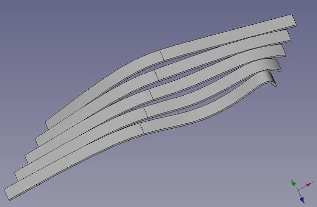
7. Jump over to the Part workbench to extrude these lines. Click on the iso curve from the treeview and then select the extrude tool from the toolbar and extrude in the desire direction, adjust the size and click ok. You have now extruded multiple profile curves.

8. You can now try extruding along a different axis to experiment.

9. A 3D offset can be applied to this extrude to finish the model
The original sketch can be altered to change the shape of the original curves. You may want to use extrusions instead of 3d offsets to get around certain offset errors.
Please note: this tutorial has been made public after spending a year plus on my Patreon page. Check out my Patreon and sign up for a qualifying level to get more tutorials like this https://www.patreon.com/mangojellysolutions
Here's the process:1. Create a sketch with two curves, individual sketches could be used but the Curves WB can be used to extract and move both curves. Think of this just as a template.
2. Go to the Curves workbench and select one curve and click the join curve tool or from the top menu; Curves >join curves. Repeat for the second curve, note: the newly created join curve may need to be expanded in the tree view and the original sketch inside visible by selecting it and pressing the spacebar.
You now have two join curves.
3. Transform one of the join curves (right click on it from the tree view and select transform). You can now create some distance between them.
4. Now create a loft or a ruled surface across these two curves using the Part workbench. Here I have chosen a ruled surface by clicking on both lines and selecting the ruled surface icon from the toolbar or from the top menu > part > create ruled surface.
5. Jump back over to the Curves workbench. Now you are going to try to emulate what rhino 3D does with tweeting using the iso curves tool. Select the surface and then click on the iso curve tool or from the top menu > curves > surfaces > iso curve. This will create an iso curve for the face. Click on the ruled surface and press the spacebar to hide it leaving the iso curves visible.
6. You can adjust the amount of lines if desired from the data tab (Number U, Number V). You need to set one of the number (U or V) to 0 to isolate the horizontal curves.
7. Jump over to the Part workbench to extrude these lines. Click on the iso curve from the treeview and then select the extrude tool from the toolbar and extrude in the desire direction, adjust the size and click ok. You have now extruded multiple profile curves.
8. You can now try extruding along a different axis to experiment.
9. A 3D offset can be applied to this extrude to finish the model
The original sketch can be altered to change the shape of the original curves. You may want to use extrusions instead of 3d offsets to get around certain offset errors.
Please note: this tutorial has been made public after spending a year plus on my Patreon page. Check out my Patreon and sign up for a qualifying level to get more tutorials like this https://www.patreon.com/mangojellysolutions
Comments
Post a Comment