A helix whether 2D or 3D, can be used as scaffold geometry. By using such operations as a sweep we can create such objects a internal and external threads, compression springs, Archimedes screws, circular spiral stair cases, the list goes on. The process of creating these models is more or less the same in all CAD packages. This tutorial will concentrate on repeating a part across a helix path. For this we will be using the workbench known as Lattice 2, with it's powerful array and placement tools it should make the process of creating such structures
To install Lattice 2 go to the top menu > tools > add on manager and install the WB.
Jump to the Part WB. Select the top menu > part > create primitives ... A new panel will appear where you can select the helix from the drop down and enter some parameters (see screen shot) and hit create.
Jump to the Part WB. Select the top menu > part > create primitives ... A new panel will appear where you can select the helix from the drop down and enter some parameters (see screen shot) and hit create.
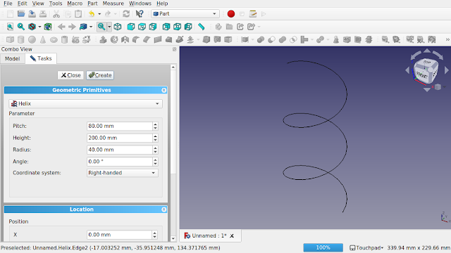
The helix is a 'Part Feature' object so it will inherit the base properties. Additional properties are also available and some of them are as follows:
Pitch: Distance between two consecutive turns of the helix.
Height: Height of the helix.
Radius: Starting radius. If this is set to zero degrees then the helix has a constant radius.
Angle: Defines of the outer shape and is in a range of -90 degrees to 90 degrees with a default of 0 degrees. For a cylindrical the helix this will need to be left at the default of zero degrees. If the values is greater or smaller than zero then the helix become conical in shape.
Coordinate System: The travel of the helix with the options of right-handed (default) for counterclockwise rotation or left-handed for counterclockwise rotation. The helix turns run from bottom to top (upwards direction).
Hit the close button and now navigate to the lattice wb. Select the top menu > lattice2 > Linear Array >Linear Array Span / N. This will create a new object with 4 kites. Right click, transform and rotate so it's pointing upwards through the middle of the helix.

Click on the linear array and on the data tab increase the count and the span end properties so that the linear array is the same height as the helix. Note the height of the helix and the span end match.

Ctrl click the linear array and then the helix from the treeview and then select the top menu > lattice2 > project array. An error will occur regarding Tangent U factor. Continue this as we will correct next.

Click on the new 'Project' icon in the treeview and change the orientation mode on the data tab to 'keep'. The placement will be mapped against the helix.

Now we can create something to wrap around this helix. I am going to keep it simple and use a simple rectangle cube. We can add a placement to this but I'm not going to over complicate, I will keep that for another tutorial. Navigate to the part workbench and create a cube and give it some dimensions.
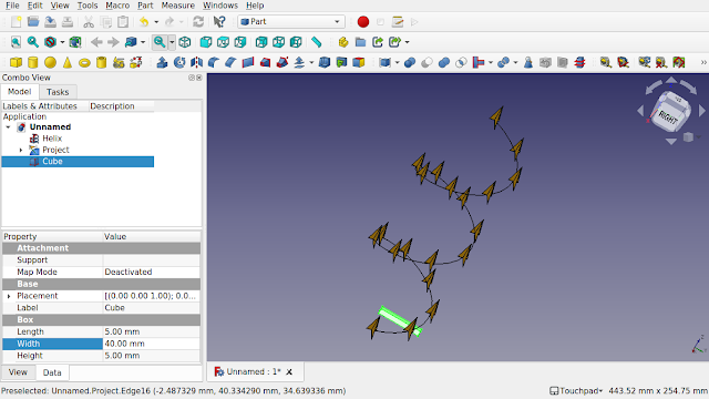
Navigate to the lattice workbench and select the cube and ctrl select the 'project' from the treeview. Click the top menu > lattice2 > populate with copies > populate with copies. The helix will be populated.

Drill into the new object in the treeview and select the 'project' and play with the orientation mode. Here I have changed it to 'along gap'.

Now we can affect the rotation of the original cube by selecting it from within the treeview, right click and rotate. Here I have used the top view and rotated the cube and hit ctrl r as I am rotating to see the effect. Once I am happy I can hit ok and then alter some other settings.

Here I have gone back to the linear array and increased the count to 50.

Once you are happy then click on the original cube in the treeview and press the spacebar to hide it. Do the same for the helix and project.

Now we can make this one object. Jump over to the part workbench, select the populate project with cube and click on the top menu > part > boolean > union. This will create a fusion.

Now you can use this as you would a part object. Remember you can use the 'project' again and apply another part, sketch, object etc to it.
Comments
Post a Comment