FreeCAD is a powerful open-source CAD tool used by engineers and designers worldwide. If you need to export multiple selected objects to separate files, this handy macro can save you time and effort. This macro will take the selected objects i.e. a number of separate extrudes that you have ctrl selected from screen, and export them out as individual step files into your chosen directory. A demonstration of this macro can be found on my youtube channel https://youtu.be/IapVaYQWN2M. To use the macro take a copy of the below text.
Load freeCAD and from the top menu select macro > macros. You will see the Execute Macro popup.
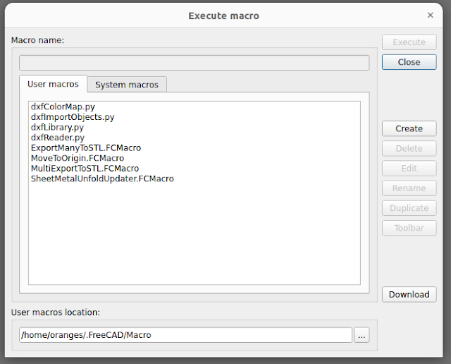
Click on the create button and give your macro a name in the popup that follows.


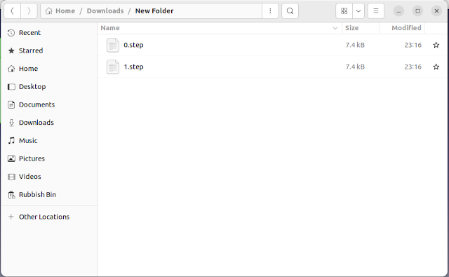
You now have all your exported step files.
Macro Code
from PySide import QtGui

folder = str(QtGui.QFileDialog.getExistingDirectory(None, "Select Directory"))
a = Gui.Selection.getSelection()
count = 0
import ImportGui
options = None
if hasattr(ImportGui, "exportOptions"):
 options = ImportGui.exportOptions(".step")
for b in a:
 objs = []
 objs.append(b)
 file = folder+"/"+str(count)+".step"
 ImportGui.export(objs, file, options)
 count = count + 1


Click OK. A new window will appear where you can paste the macro into it and save (ctrl s or top menu > file > save).

The macro is now ready to use.
Using the macro
An example of using the macro. Let's say we create a project with two cubes within. Shift or ctrl select both cubes from the treeview so they are both selected.

Select top menu > Macro > macros and then select the macro from the popup window.
Click on the execute button to run the macro. The popup will close and you will see the next window will ask you for the location of where you want to export the individual step files to.
Click the choose button and the window closes followed by the step file options. Select the options you want if needed.
Click OK. Navigate to the folder which was chosen and you will find the files of each item you selected in the treeview.
You now have all your exported step files.
You know me as Felsin Ferguson over on Youtube - Following up on my reply to your reply on this macro in the comments.
ReplyDeleteI think everybody can agree that we can do better than naming the files "0.stl", "1.stl", etc... So I took the liberty of doing a fiddle, and here's my version for doing multiple STL exports - Released to the public domain, yadda, yadda, whatever.
from PySide import QtGui
folder = str(QtGui.QFileDialog.getExistingDirectory(None, "Select Directory"))
a = Gui.Selection.getSelection()
import Mesh
for b in a:
objs = []
objs.append(b)
Mesh.export(objs, folder+"/"+b.Label+".stl")
And I see now why the objs = [] is inside the for loop. Guess my nose was a bit "off" :)
Ugh... Looks like it ate the indentation. Should be everything flush-left up to and including the "for" line, and the next 3 lines need one indent each.
Deletefrom PySide import QtGui
Deletefolder = str(QtGui.QFileDialog.getExistingDirectory(None, "Select Directory"))
a = Gui.Selection.getSelection()
import Mesh
options = None
if hasattr(Mesh, "exportOptions"):
options = Mesh.exportOptions(".stl")
for b in a:
objs = []
objs.append(b)
file = folder+"/"+b.Label+".stl"
Mesh.export(objs, file)
I was thinking the same thing also.