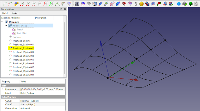
I talked about creating a Rhino3D tween curve on my Patreon page a few weeks ago (https://www.patreon.com/posts/75954207) and an idea that I have to get this working as a macro in #FreeCAD. But I thought I try to make a few intermediary macros to get myself back into the swings of programming again. I already created the 'curve to freehand b-spline' in a previous post but now I want to take this a step further and create a 'ISO curve to freehand b-spline mesh'. This means that there would be a fully eatable mesh that can be lofted, approximated with some kind of NURBS surface such as a Gordan surfaced or even a plane loft or ruled surface. Building it with Freehand B-Splines will allow a user to double clicking the individual curves to edit the mesh via the control points.
The ISO surface interrogates a selected surface and creates a UV grid which follows the contours. My idea is to take this ISO grid and make it fully editable as a mesh allow the resulting surface to be deformed.
Referring back to the code supplied by Chris G, the creator of the curves workbench in FreeCAD, the code to create a Freehand B-Spline is as follows:
from freecad.Curves import gordon_profile_FP as GP
sub = []
# If the Spline is snapped to other shapes
# add a link to these shapes. For example :
# sub = [(obj1, ("Edge1",)), (obj2, ("Face1",))]

# the interpolation points
pts = [FreeCAD.Vector(0, 0, 0), FreeCAD.Vector(5, 0, 0), FreeCAD.Vector(10, 0, 0)]

# the type of each point.
# 0 = free point
# 1 = point snapped to a shape of the sub list
# For example, typ = [1, 0, 1]
# means that the first point will snap to the fist shape of the sub list
# and the third point will snap to the second shape
typ = [0, 0, 0]

fp = FreeCAD.ActiveDocument.addObject("Part::FeaturePython", "Freehand BSpline")
GP.GordonProfileFP(fp, [], pts, typ)
GP.GordonProfileVP(fp.ViewObject)
fp.recompute()
So far my code gets as far as creating the freehand b-splines for each of the edges of the ISO curves. I have listed this as 'work in progress' below. At the moment I create the mesh as per the selected ISO grid but I am still wondering how this is going to work and whether I should just allow for either U or V rather than both. My thoughts is connect all U to V or vice versa as sub objects. This will mean when one freehand b-spline is edited the sub objects will follow. It might be worth colouring the splines that can be edited to distinguish them from each other.
This is what I have so far:
from freecad.Curves import gordon_profile_FP as GP
s = Gui.Selection.getSelectionEx()[0]
o = s.Object
u = o.NumberU
v = o.NumberV
mode = "u"
numberOfControlPoints = v
count = 0
for edge in o.Shape.Edges :
count = count + 1
if mode != "v" and count > u:
mode = "v"
numberOfControlPoints = u
pts = edge.discretize(numberOfControlPoints)
print(pts)
typ = [0] * numberOfControlPoints
# Create the bspline.
# Name will be appended with a unique extension if already exists
fp = FreeCAD.ActiveDocument.addObject("Part::FeaturePython", "Freehand BSpline")
GP.GordonProfileFP(fp, [], pts, typ)
GP.GordonProfileVP(fp.ViewObject)
fp.recompute()

take a look at the SilkWB (https://github.com/edwardvmills/Silk). though not exactly what you are trying to do, the ControlGrids are similar in a way, and may be useful to incorporate into what you are doing
ReplyDelete