Czechia: The Land of Lookout Towers
Did you know that the Czech Republic has more tourist watch towers than any other country in the world? Over 300 towers (and counting) dot the Czech landscape. Many of these architectural gems are free to the public and serve not just as observation points, but as historical monuments that span centuries, from the late 1800s through both World Wars and into modern times.
As new towers continue to be built, the tradition is still very much alive. These structures are more than just attractions; they offer a view, both literal and historical, into the country's rich and evolving past.
From Travel Photography to 3D Miniatures with FreeCAD
Jan travels across Czechia photographing these towers, then returns to the digital workshop to recreate them using FreeCAD. His process involves:
-
Capturing real-world photos of towers
-
Modeling each structure in FreeCAD
-
Using standard tools and macros (including a custom random stone macro)
-
3D printing the models to scale
The result? Beautiful, highly detailed miniatures that preserve both the aesthetic charm and architectural accuracy of these towers.
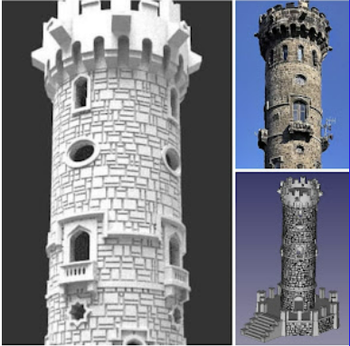
Example: Decinsky Sneznik Tourist Lookout
One standout model is the Decinsky Sneznik tower, Jan’s first project using his random stone macro to generate a realistic stone texture pattern. The printed model successfully captures the unique, weathered look of this iconic structure.
This is just one of many towers in Jan’s growing collection.

Dalimilova tourist lighthouse, an earlier model that took some computation time to complete the linear and polar calculations.

A frequent contributor to the FreeCAD Facebook group, Jan has numerous posts that showcases his skills in building these amazing structures. Starting as a Christmas project he has gone on to complete close to a dozen structures at time of writing and is still growing his collection.
Earlier post from the designer reveal the secret behind some of the models. With standard tools and workbenches in FreeCAD Jan uses what he describes as a 'mother structure', a central vertical pole with two staggered bricks radiating out. The use of polar and linear array tools complete the brick work effect.

In later models Jan flexes his programming skills taking the generation of the detail of his towers to another level. By coding a python macro to generate random stone work he can generate models with higher realism allowing him to tackle older structures in much more detail. Looking at the code of the macro the basic shape is created as a skeleton such as a truncated cone. The top and bottom radius, height etc are all configure before generation. After the macro is run each brick is generated as a separate shape which can be fused into the main structure. Other macros include linear brickwork, roofing tiles for both slanted and circular roofs, clad work etc.
I for one will be keeping an eye on this contributor who is pushing the boundaries and using Freecad in a unique way. I may even give the macros and techniques a go myself as where I live there is a large history of mining. All over the county there are mine stacks that have been standing for century's and the techniques can be easily transferred to these structures.

All screenshots originate from the FreeCAD group on Facebook.
Why This Matters for the FreeCAD Community
Jan’s work highlights the power of FreeCAD beyond engineering or product design. It’s a great example of how open-source CAD tools can be used for:
Historical preservation
Architectural modeling
Tourism and cultural projects
Hobbyist and maker creations
Get Involved
Interested in seeing more of Jan’s work? The creator has now made the models available via printables.
https://www.printables.com/cs/social/390197-jjvcela/models
Join the FreeCAD Facebook group and explore how others are using FreeCAD in creative, unexpected ways.
FreeCAD is not just for mechanical design, it's a platform for architecture, education, and artistic expression. Stories like Jan’s remind us how flexible and inspiring open-source tools can be.
Comments
Post a Comment