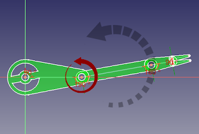
When it comes to scripting macros in FreeCAD there is one main purpose that comes to mind; animation. In 3D packages such as Maya, Lightwave, Studio max etc the subject of animation is tackled via a keyframe timeline system. You move an object from one key frame to another and the 3D package fills in the gaps. This is known as tweening as in 'in-between'. The system is intelligent enough to figure out the next frames. In CAD we don't have the same privileges because CAD is geared towards building technical models and simulation rather than animation, for example we can simulate airflow with precise parameters, test the strength of and stresses on materials, discover clashes between component within building a structure etc. These are all engineering and scientific areas and it's easy to loose track of the fact that when we look at the earlier 3D packages mentioned we are in the subject area of entertainment i.e. film, TV, games etc
There are a number of options in FreeCAD to create and control animation simulations. Depending on the reason for the animation then we may not even have to write a single line of code. When we do a simplistic animation which requires a number of objects to move over time, then writing the least code possible and leveraging constraints or manipulating object parameters such as position and rotation makes our life easier.
There are a number of workbenches called assembly's. These allow you to place (assemble) your objects (parts) together in what is known as an 'assembly'. Constraints are made against each part, moving one part will affect all other parts in constraint. This movement can either be done manually or by code.
By clicking and dragging a part or changing the properties through the FreeCAD's user interface we can see our assembly animate but if we want to playback this movement or run a simulation with certain parameters such as speed, distance etc then we need code.
Some assembly workbench allow for us to create an exploded assembly through recording our movements to show how parts fit together. When we are looking at more complex areas such as the kinematics of suspension systems to the mechanical movement of complex parts, relationships can be created with constraints. Manually moving parts with the mouse will allows us to see the effect on others parts, if we want our animation to be permanent then we also need to write some code. The Assembly 4 workbench does have a utility which can control movement via changing the value of variables, allowing us to play our animation but this is very basic and doesn't have the ability to save. Scripting a macro allows you full control over your animation whilst leveraging these tools.
Please be aware that the workbench know as the 'Animation Workbench' is no longer in active development so is not supported in later versions of FreeCAD
We will look at three methods of animation along with simple examples to understand how these work. Firstly by controlling animation directly through Python without using any supporting assembly tools or workbenches, a "vanilla" environment. Then we will look at two of the most used workbenches; Assembly 2 plus and Assembly 4
Assembly 2 Plus and Assembly 4 In a Nutshell
The two workbenches offer two different ways to work with parts. Assemblies allow for each part to be either created in the same or separate document(s) and then positioned relative to the assembly and contained parts. Assembly 2 plus offers a number of constraints; you add to faces and / or edges of opposing parts, combine them together to create more complex ones and observe the results on your assembly. Parts can be fixed in 3D space to allow others to be constrained in this fixed point creating a direct or indirect relationship. For instance you can make the faces of planes or spheres coincide with each other, doing this with a sphere and the shell of another sphere with similar diameter will create a simple ball joint. We can then attach one end to an arm which rotates around a fixed point offered by a part such as a bolt which has been set with the fixed property.
The Assembly 4 workbench works differently. It offers two ways to create assemblies by allowing parts to be given one or more local coordinate system(s) (LCS) to align them with others. This also allows for a master sketch concept where a basic bone system can be created for a more kinematic approach.
Kinematics
Forward Kinematics
When a bone chain is chained from parent to children it is know as FK if you rotate a parent bone all of the children will follow. If we have a three bone chain Bone A , B and C, rotating Bone A will cause Bone B and C to follow, Bone A is the parent of Bone B, Bone B is the parent of Bone C. Rotating Bone A rotates Bone B, Bone B is the parent of C so it to will follow. Rotating just Bone B with cause Bone C to rotate but Bone A will stay where it is allowing Bone B to pivot at the attachment point. This means that all movements are arc or curved based you have to rotate each bone separately.
Inverse Kinematics
With IK you loose the the parent child effect but you gain a more natural movement. Moving a bone in the chain causes all the other bones to follow in a dragging motion. Think of it as a string of paper clips linked together. Move the last paper clip and all the rest will follow. This gives movement that follows lines rather than arcs as the movement will follow the point of drag.


Comments
Post a Comment