Multi Body Hinged Boxed with Shape Binder
We are going to create a non symmetric box in FreeCAD with basic pin hinges for 3D printing. We will utilise the part design shapebinder for placement and to act as a simple master sketch between the hinges of the bodies allowing for diameter changes in the hinges to take effect on both bodies.
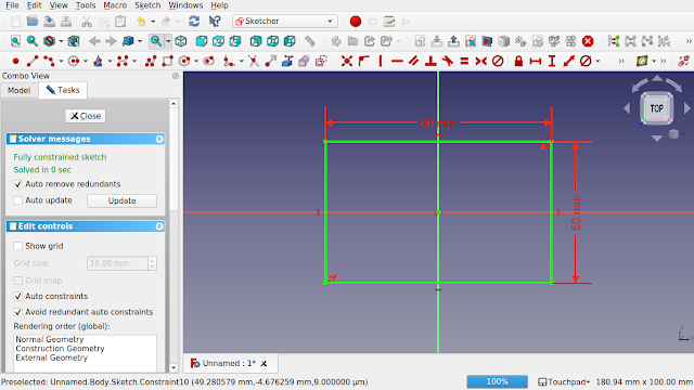
1. In the part design create a body and then create a sketch on the x/y plane. Create a simple box say 80 mm x 50 mm constrained to the centre with symmetric constraints to the point of origin.
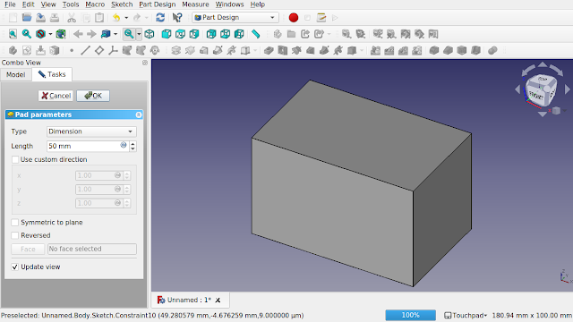
2. Close the sketch and pad to 50 mm. This will be the lower body of the box.
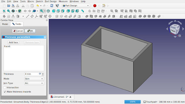
3. Select the top of the box and select the thickness icon to create a void with 4 mm thick walls. Select the option to push the thickness inwards.
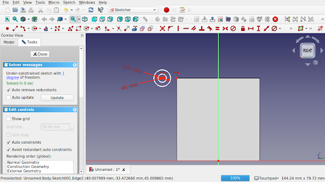
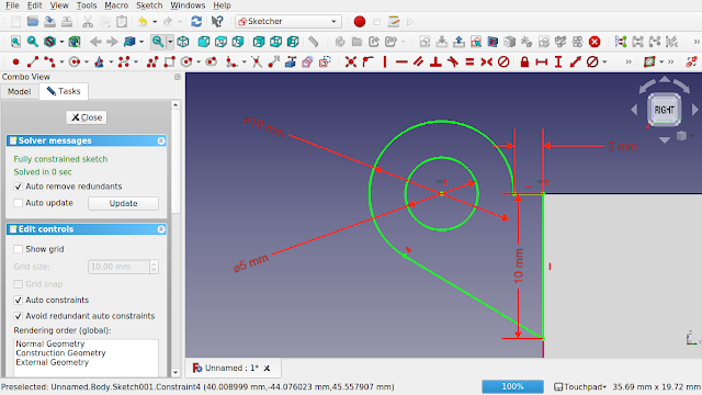
4. Select OK and bring the view around to the right. Select the face and create a sketch on the face. Bring in the left top point by using the create an edge linked to external geometry tool. Create two concentric circles to each other, a 5 mm and a 10 mm diameter circle. Make sure the centre points are concentric to each other and horizontally constrained to the top left point of the box.
5. Create the hinge as per the sketch.
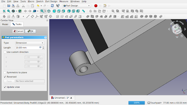
6. Now pad the hinge. You may have to send the hinge backwards (reversed). Don't worry if you don't see a pad and everything disappears, the minute you check the reverse tick box then you will see the pad. We will go with 10 mm for now.
7. Click OK and select the pad in the treeview.
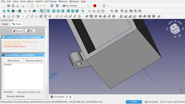
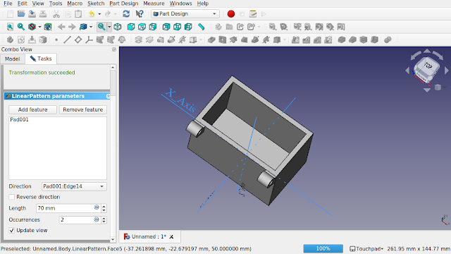
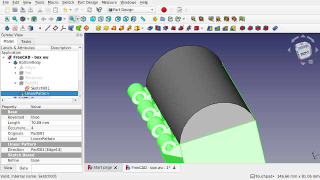
8. Click on the linear pattern icon from the part design workbench, you will see the following screen.
9. Swing the view around and zoom out so you can see the whole box. We need to make a linear pattern along the top edge. Scroll down the option on the left hand side of the screen and click on the direction drop down box and select 'select reference...' option. Now select the top edge of the box. You will see a red hinge appear and the drop down will show the name of the edge. We can now adjust the length and occurrences.
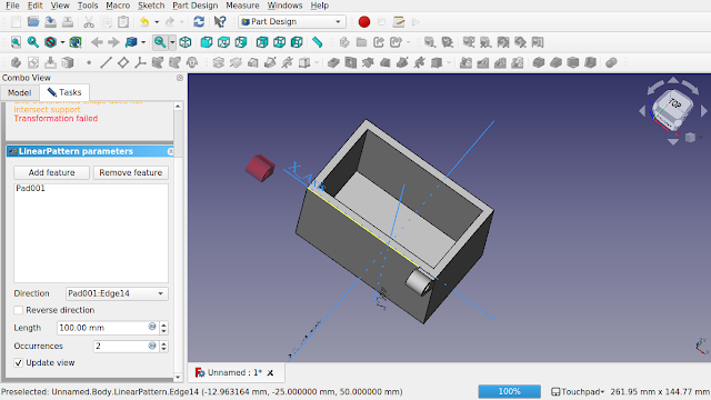
10. The box is 80 mm long, the hing is 10 mm. 80 - 10 = 70. Enter 70 mm in length and click off the box into some blank space. You will see the back hinge move into place.
11. Set the occurrences to 4.
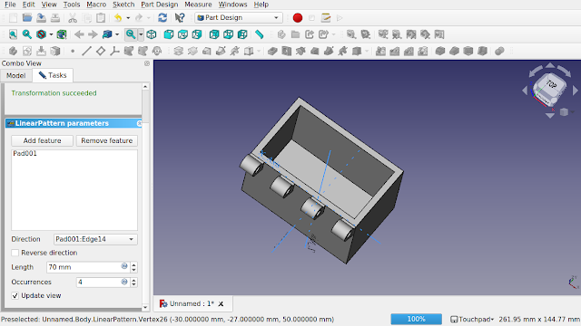
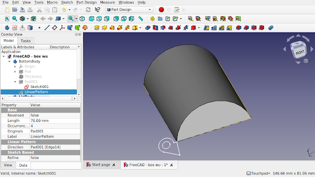
12. Click OK. You have modelled the first part of your box.
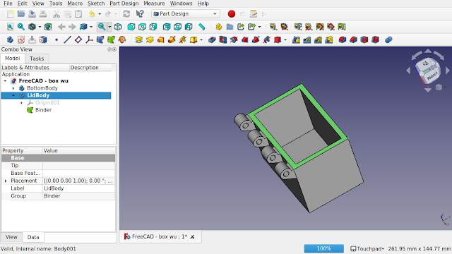
13. Create a new body (but not a new sketch). This will be for the lid.
14. Click the top face, the lip that runs around the bottom box and select the sub-shape binder tool. The top face will look like it has a orange overlay placed on top of it. This is the shape binder. Note the shape binder inside the body.
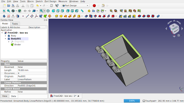
15. For ease of this tutorial I have renamed the top and bottom bodies as you can see in the treeview
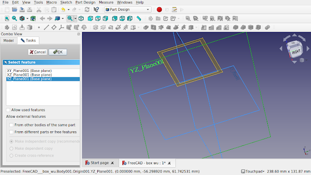
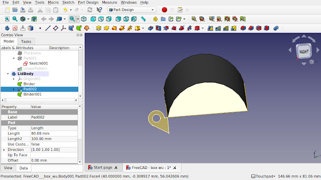
16. Hide the bottom body and click on some blank space in the view so nothing is selected and create a sketch. Select the YZ plane.
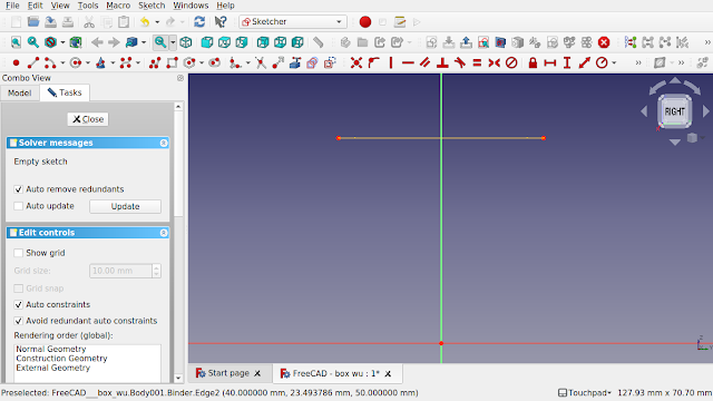
17. A new sketch will open and you will see the side of the shape binder. Import the two corner points
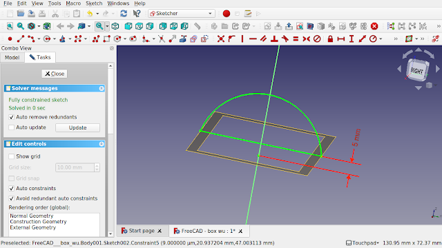
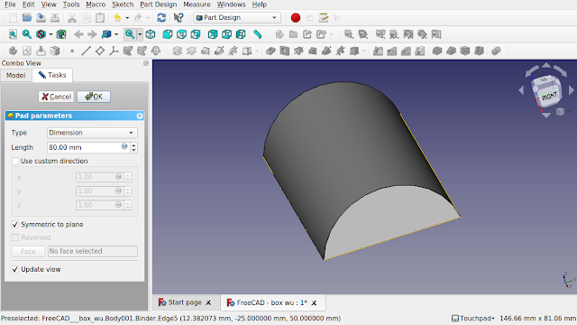
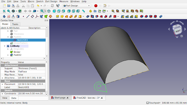
18. Sketch an arc and close the sketch with a line.
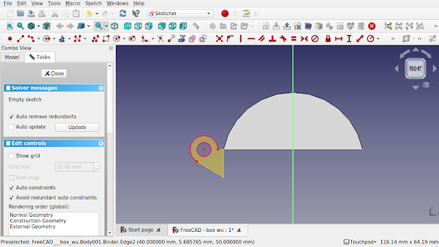
19. Close the sketch and pad it by 80 and make it symmetrical to plane as the sketch runs through the centre. The whole sub-shape binder should be covered.
20. Hit close and then select the bottom body from the treeview and press the space-bar to make the body visible. Expand the treeview nodes and find the hinge sketch and make it visible. It will be nested in the pad before the linear pattern.
21. Hide the linear pattern to isolate the sketch in the view.
22. Click on the sketch and make sure that the lid body text in the treeview is bold (active body)
23. Click on the sub-shape binder to create a binder in the lid body.
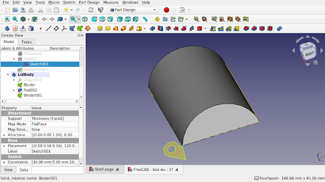
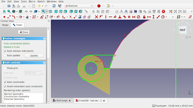
24. Click on the face of the lid nearest to you.
25. Now make sure the sketch you created the shape binder from is hidden otherwise you will not be able to import the external geometry. Create a sketch on the face and import the two circles from the shape binder.
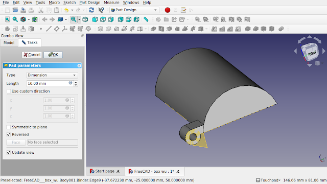
26. Use the shape binder imported geometry and the face geometry to create your hinge.
27. Close and pad, we will change the position and size of the pad later.
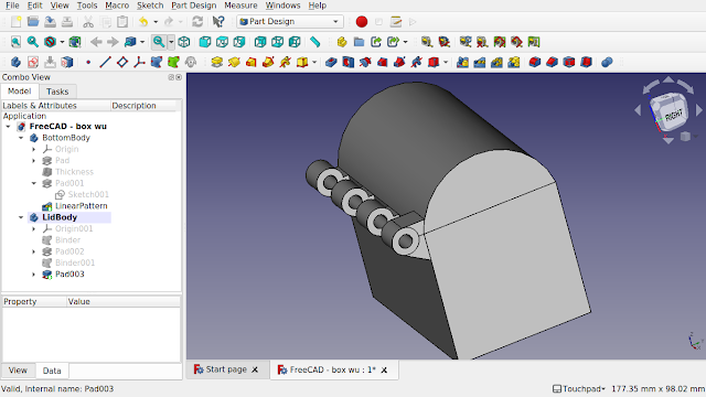
28. Click OK. We can now hide the shape binders. Click on the bottom body and make it visible by pressing the spacebar. Make sure the last action in the bottom body is also visible. You can see how these will line up.
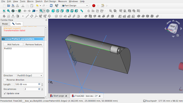
29. Click on the last pad in the lid body and click on the linear pattern button on the part design toolbar.
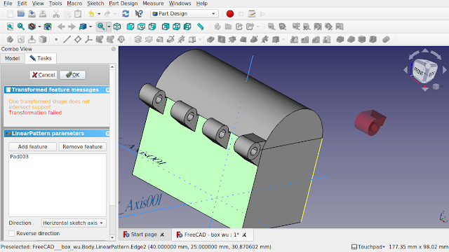
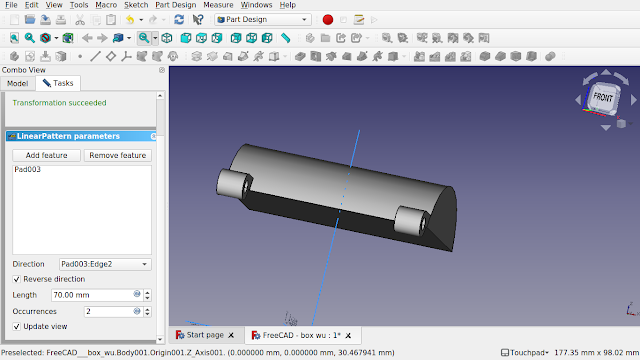
30. Click on the bottom box and press the space bar to make it hidden. Scroll down the left hand panel to the bottom and click on the direction drop down box and click the option "Select reference ...". Select the bottom edge of the lid where the hinge runs. The edge name will appear in the drop down.
31. Keep the occurrences as 2 and change the length to 70 mm.
32. Don't OK this task but click on the model tab and select the bottom body and make it visible along with its last action, the linear pattern.
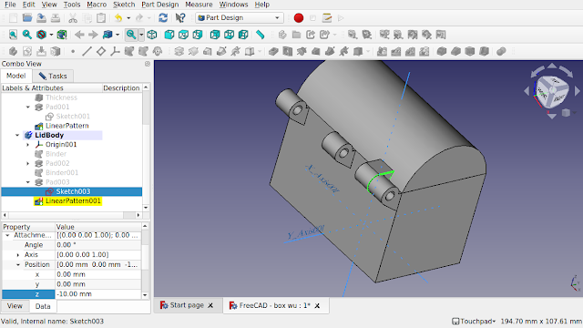
33. We need to adjust the sketch for the hinge of the top lid. Find the sketch of the hinge, it should be above the linear pattern, make it visible and locate its attachment properties on the data tab. Drill in to find position and the Z axis.
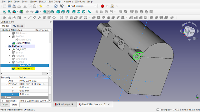
34. Move the sketch back so its behind the bottom body hinge as at the moment they are over-lapping.
So Z will equal -10 mm. Refresh (ctrl + R) and the hinge will move but the linear pattern will go into error. That's because we now have to reduce the length of the linear pattern.
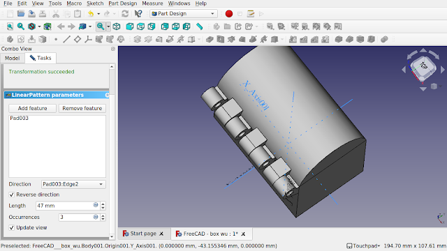
35. Go back to the task tab and set the occurrences to 3 and the length to 50 mm. And then set the bottom linear pattern to occurrences 4 length 70 mm.
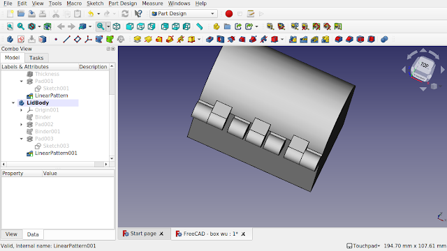
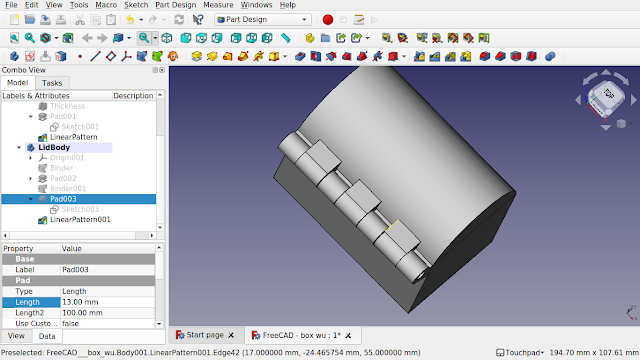
36. Modify the length of the linear pattern for the lid to allow the hinges to but up against each other.
37. Modify the length of the pad of the hinge for the top lid to get a better fit.
We are going to create a non symmetric box in FreeCAD with basic pin hinges for 3D printing. We will utilise the part design shapebinder for placement and to act as a simple master sketch between the hinges of the bodies allowing for diameter changes in the hinges to take effect on both bodies.
1. In the part design create a body and then create a sketch on the x/y plane. Create a simple box say 80 mm x 50 mm constrained to the centre with symmetric constraints to the point of origin.
2. Close the sketch and pad to 50 mm. This will be the lower body of the box.
3. Select the top of the box and select the thickness icon to create a void with 4 mm thick walls. Select the option to push the thickness inwards.
4. Select OK and bring the view around to the right. Select the face and create a sketch on the face. Bring in the left top point by using the create an edge linked to external geometry tool. Create two concentric circles to each other, a 5 mm and a 10 mm diameter circle. Make sure the centre points are concentric to each other and horizontally constrained to the top left point of the box.
5. Create the hinge as per the sketch.
6. Now pad the hinge. You may have to send the hinge backwards (reversed). Don't worry if you don't see a pad and everything disappears, the minute you check the reverse tick box then you will see the pad. We will go with 10 mm for now.
7. Click OK and select the pad in the treeview.
8. Click on the linear pattern icon from the part design workbench, you will see the following screen.
9. Swing the view around and zoom out so you can see the whole box. We need to make a linear pattern along the top edge. Scroll down the option on the left hand side of the screen and click on the direction drop down box and select 'select reference...' option. Now select the top edge of the box. You will see a red hinge appear and the drop down will show the name of the edge. We can now adjust the length and occurrences.
10. The box is 80 mm long, the hing is 10 mm. 80 - 10 = 70. Enter 70 mm in length and click off the box into some blank space. You will see the back hinge move into place.
11. Set the occurrences to 4.
12. Click OK. You have modelled the first part of your box.
13. Create a new body (but not a new sketch). This will be for the lid.
14. Click the top face, the lip that runs around the bottom box and select the sub-shape binder tool. The top face will look like it has a orange overlay placed on top of it. This is the shape binder. Note the shape binder inside the body.
15. For ease of this tutorial I have renamed the top and bottom bodies as you can see in the treeview
16. Hide the bottom body and click on some blank space in the view so nothing is selected and create a sketch. Select the YZ plane.
17. A new sketch will open and you will see the side of the shape binder. Import the two corner points
18. Sketch an arc and close the sketch with a line.
19. Close the sketch and pad it by 80 and make it symmetrical to plane as the sketch runs through the centre. The whole sub-shape binder should be covered.
20. Hit close and then select the bottom body from the treeview and press the space-bar to make the body visible. Expand the treeview nodes and find the hinge sketch and make it visible. It will be nested in the pad before the linear pattern.
21. Hide the linear pattern to isolate the sketch in the view.
22. Click on the sketch and make sure that the lid body text in the treeview is bold (active body)
23. Click on the sub-shape binder to create a binder in the lid body.
24. Click on the face of the lid nearest to you.
25. Now make sure the sketch you created the shape binder from is hidden otherwise you will not be able to import the external geometry. Create a sketch on the face and import the two circles from the shape binder.
26. Use the shape binder imported geometry and the face geometry to create your hinge.
27. Close and pad, we will change the position and size of the pad later.
28. Click OK. We can now hide the shape binders. Click on the bottom body and make it visible by pressing the spacebar. Make sure the last action in the bottom body is also visible. You can see how these will line up.
29. Click on the last pad in the lid body and click on the linear pattern button on the part design toolbar.
30. Click on the bottom box and press the space bar to make it hidden. Scroll down the left hand panel to the bottom and click on the direction drop down box and click the option "Select reference ...". Select the bottom edge of the lid where the hinge runs. The edge name will appear in the drop down.
31. Keep the occurrences as 2 and change the length to 70 mm.
32. Don't OK this task but click on the model tab and select the bottom body and make it visible along with its last action, the linear pattern.
33. We need to adjust the sketch for the hinge of the top lid. Find the sketch of the hinge, it should be above the linear pattern, make it visible and locate its attachment properties on the data tab. Drill in to find position and the Z axis.
34. Move the sketch back so its behind the bottom body hinge as at the moment they are over-lapping.
So Z will equal -10 mm. Refresh (ctrl + R) and the hinge will move but the linear pattern will go into error. That's because we now have to reduce the length of the linear pattern.
35. Go back to the task tab and set the occurrences to 3 and the length to 50 mm. And then set the bottom linear pattern to occurrences 4 length 70 mm.
36. Modify the length of the linear pattern for the lid to allow the hinges to but up against each other.
37. Modify the length of the pad of the hinge for the top lid to get a better fit.
Comments
Post a Comment