
Hexagon Celled Curved Surfaces in FreeCAD

Hexagon mesh and structures feature heavily in the CAD industry.  Being a naturally strong structure they are built by insects to build homes so it would be only common sense to utilise them in human structures for their strength and reliability.

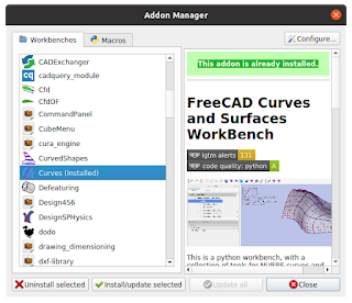
For this tutorial we will be creating a hexagon 'Bee Hive' surfaces using the curves workbench in FreeCAD.  To do this we will need the curves workbench installed (from the tools menu > add on manager > workbench tab > curves.

And from the same location click on the Macros tab and select the honeycomb macro.

FreeCAD will ask you to restart which you must do for these to take effect.  Please not: The macro when first run will create a file, you must restart FreeCAD again once this file is created.  Subsequent use doesn't need a restart.

We are going to start creating our object first using a simple curved surface.  We will start with an extruded curve.

1. Create a  new file.

2. Jump into the sketcher workbench and create a curve, I have used a b-spline


3.  Close the sketch and jump into the part workbench.  Extrude the curve choosing the correct axis for your extrusion.  I have selected the Z axis.


4.  Jump over to the Curves workbench, select the face of the extrude and then go to the top menu Surfaces > Map sketch on surface.  You will see a icon appear in the treeview, expand this out so you can see the mapped sketch.


5. Double click on the map sketch.  At this point there are one of two routes to follow depending on how the sketch has been (or not been) mapped to the surface.  If you see the following; really thin blue rectangle or a tiny blue square that doesn't conform to the surface and instead of length constraints there are block constraint then we need to keep following the instructions. If not jump to step 13


6.  So we have the problem above and the mapping has failed.  This is not an issue that we can't resolve.  

First delete the sketch on surface and mapped sketch from the treeview reverting back to what we see in the screen shot on step 3.

7.  We now need to create a new sketch via the sketcher and map that to the face.  To do that we need the width and height of our surface as if it was flattened.  This is very simple to do by using the GeomInfo tool.  To activate the tool click on the top menu Misc. > GeomInfo.  This will activate the small info icon in the toolbar.

8.  Now click on the top edge of the surface.  Some information will be displayed giving details of the edge, take note of the length.  Repeat with one of the vertical edges.

9.  This surface is 116.58 x 100.   Create a new sketch and create a rectangle with the dimensions constrained to the centre.


11.  Make a couple of the lines intro construction geometry, I used the two sides, it's just to show how normal and construction geometry will be displayed.  This boarder sketch will become all construction geometry.  Close the sketch, locate and select it in the treeview, we can now access its properties tab.  We are going to map it to the face of the object.  Click on the button at the end of the map mode field.  When the attachment window is shown select the face of the surface.

12.  Click OK to close the window. Change to the curves workbench and click on some spare space to make sure nothing is selected. 

13.  Now we can create our honey comb.  Click on the top menu > tools > macros ... and from the popup window select the user macros tab and select the honeycomb macro.

14.  Double click the macro or select the execute button.  If this is the first time you will see the following message. Click the create file button, save your document and then restart freeCAD (you only need to do this once) 


15. Once the file has been created we will see another information dialog box showing that freeCAD has successfully created the file.  Click OK.

16.  Go back to the execute Macros window, notice an additional file?  Don't execute this file, execute the original macro.


17.  After a short wait a HoneyComb object will appear in both the treeview and the 3D view.  We can customise this object to our needs.


18.  We now have to position this object.  Click on the extrude surface and press the spacebar to hide it.  We want to deal with just the sketch and our honey comb object.  Expand the properties of the object to access the orientation.  Change the angle and orientation so it lays flat against the sketch.


19.  Come down to the honeycomb properties and set the boarder height offset to 0, border offset to 0 and the Elliptical Grid to false.


20.  Change the height, width and length properties to we have enough height as shown.  We will adjust the properties in accordance to the plane you created the sketch on.  In my case it was the height and length.


21.  Now change the radius (to create larger hexagons) and the width (to increase the coverage)


22.  Now we can transform this into position using the placement and make any finer adjustments.


23.  Click on the original extrude surface in the treeview and make visible.


24  Now's time to map the sketch to the face.  Click on the sketch in the treeview and then click the face of the surface.

25.  Then click on the map a sketch on a surface tool or select from the top menu Surfaces > Sketch on Surface.   In the treeview we will see the sketch on surface icon and within the mapped sketch.  Our sketch is now mapped to the surface, you will notice the black line around the edge of the surface, these correspond to the boarders of the sketch that are not in construction mode.


26.  Expand the sketch on surface icon on the treeview and double click the mapped sketch inside.  Notice how this is still in line with the hexagon grid.  Close the sketch

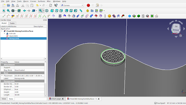
27.  We will now bind the hexagon mesh to the surface.  We could use the extra objects option of the sketch on surface against the original honey comb object but we will hit an issue.  As this is not a single face but a three dimensional object we will get extra edges.  We can see this if we try it.  Click on the sketch on surface icon in the treeview and look down towards the properties tab and locate the 'Extra Objects' field.

28.  Click the button at the end of the field and a popup will appear.  Select the 'Honeycomb'.

29.  Click OK and wait a moment.  The shape of the object will be bonded to the surface.

30.  Click on the original honeycomb object and the extrude and hide these.


Note the following which we need to resolve:

a) The sketch that appears at the edges which isn't construction geometry, we will later convert it to construction geometry, it is standard geometry just to make it easy for us to position the grid.

b) The hexagons elongate at edges.  Keeping the meshing inside the sketch boundaries resolve this issue.


c) The double edges.  Caused by the flattening of the hexagon mesh.  We resolve by extracting only need the face of the mesh with tools from the curves workbench or a draft workbench facebinder.

After resolving point b we should have something like this.  At this point it's worth resolving the border sketch issues and changing them to construction geometry.

Solving the extra edges issue:

31:  We will now make visible both the original honeycomb object and the extrude and remove the extra object from the sketch on surface property by clicking on the button on the end and selecting clear on the popup window.  If it isn't remove then it's just a refresh issue and be resolved when we reattach the object, if it bothers you that much just delete the sketch on surface icon from the treeview and use the tool again to map the sketch onto the surface

32.  Zoom in and select the face of the honey comb (there should be only one)

33.  Click on the top menu > misc > parametric solid.  This will great a brown icon in the treeview which a shell of the selected face.  Hide the original honeycomb object.

34.  Use this solid in the extra objects option.


35: We now have the hexagons on the face of the surface.  Hide the surface, sketch and solid.

36.  Now we can use the fill faces, offset etc to get the desire result.  If thickness results in error increase the separation property.  If other errors are encountered such as random hexagon faces being filled then use the part workbench along with compound explode to get to the individual faces.  From these we can do cuts, booleans and 3D offsets to fix our issues.

Comments

Popular posts from this blog

Beginners FreeCAD: Exercise 5.1 & 5.2 (Reference Images)

Welcome to the total beginners course to FreeCAD 0.20. In this is a two part lesson we will practice our tracing skill in the form of a mini project. Using the below reference photos we will create a more complex part which will consist of repeating features. We will utilise the symmetry tools to ease construction in both FreeCAD sketcher and Part Design workbench. This project work will help teach the fundamentals of freeCAD allowing a understanding of the basics but delivering this information via teaching you different workflows. In this tutorial we will be tracing photos imported into FreeCAD via the image workbench https://wiki.freecadweb.org/Image_Workbench JUMP TO IMAGES Do you want to purchase the complete series along with others and keep forever?  Check out my shop https://ko-fi.com/mang0/shop The story of this tutorial The idea and first attempt at creating this tutorial was back in FreeCAD 0.18.  The physical part itself, well, I have no idea what really it is, i...

FreeCAD For Beginners: CAD Thinking Part 1

Step-by-Step CAD Thinking FreeCAD Tutorial: Modeling a Latch Part (Part 1) Learning how to turn real life objects into CAD Models. Using FreeCAD we explain at a beginner level how to break down a physical object into its primitive shapes to digitise it into a 3D model, with this episode we are looking at a multi-part assembly, modelling each piece individually. The series aims to open your eyes and mind giving you the ground skills to pick the correct profiles, geometry and workflow when it comes to modelling your parts. This is not just for FreeCAD but for all CAD packages out there. Introduction This tutorial is the first in a series guiding you through modeling a latch assembly in FreeCAD (version 0.21) using the Part Design and A2Plus workbenches. It focuses on modeling the first part (a slotted component) by selecting the top profile to create a slot and adding side arcs, emphasizing CAD thinking to break down complex shapes into primitives. The tutorial highlights model stability...

Beginner FreeCAD Tutorial 14: Reference Document for Exercise 1

This tutorial focuses on modelling a deck eye plate. These items are normally made of stainless steel with some kind of galvanised coating to stop corrosion. They are used in many industries but are most commonly found around boats, ships, sail lofts and docks where they play an important part in marine industry. Finding their use in many applications, they are often wall mounted acting as lashing points for mooring and for tying down sails or canopies. They can even be used for domestic use around the house and garden, for example to anchor ropes, cords and lines. So if your into 3D printing your finished creations, you can make use of the finished result.   Disclaimer : The strength of the part will depend on the internal structure, settings of the slicer and the material it has been printed on.  This will limit its application as failure of the part, damage to property and injury is a possibility.  These items are normally made of steel and are tested to take a...